MGN12H Miniature Linear Guide: The Ideal Choice for High-Precision & Compact Motion
Mar 27, 2026
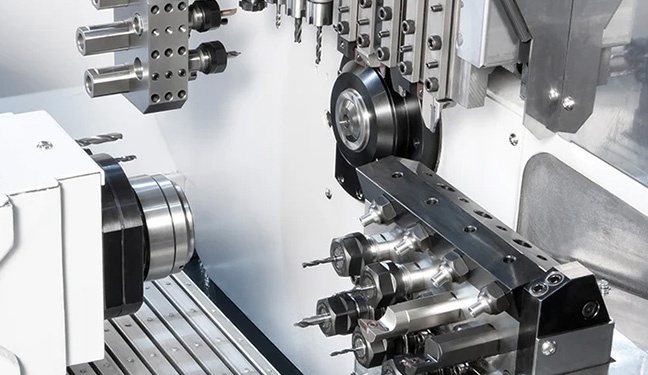
In automation, precision instruments, 3D printing and other fields, the demand for compact, high-precision linear motion continues to rise.
Shuntai’s MGN12H miniature linear guide is a core transmission component designed specifically to meet these demanding applications.
With a compact width of 12mm and multiple length options including 100mm, 300mm, 500mm, and 1000mm, it provides engineers with a solution that balances performance and flexibility.
1. What is the MGN12H Miniature Linear Guide?
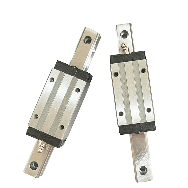
MGN12H is part of the miniature linear guide series, where “12” indicates a rail width of 12mm, and “H” stands for high-load block design.
This type of guide achieves linear motion through ball rolling, unlike traditional sliding contact, enabling stable high-precision positioning within extremely small installation spaces.
As a flagship product under the Shuntai brand, the MGN12H integrates core precision components such as bearings, featuring industrial-grade quality with long service life and high rigidity.
It is widely suitable for precision positioning, processing, and conveying in automated systems.
2. Core Technical Advantages of MGN12H
① Ultra-High Precision & Repeatable Positioning
The MGN12H adopts a precision ball rolling structure, minimizing displacement and return errors.
Whether for wafer alignment in semiconductor equipment or focus adjustment in optical instruments, it delivers micron-level accurate positioning, ensuring consistent motion during long-term equipment operation.
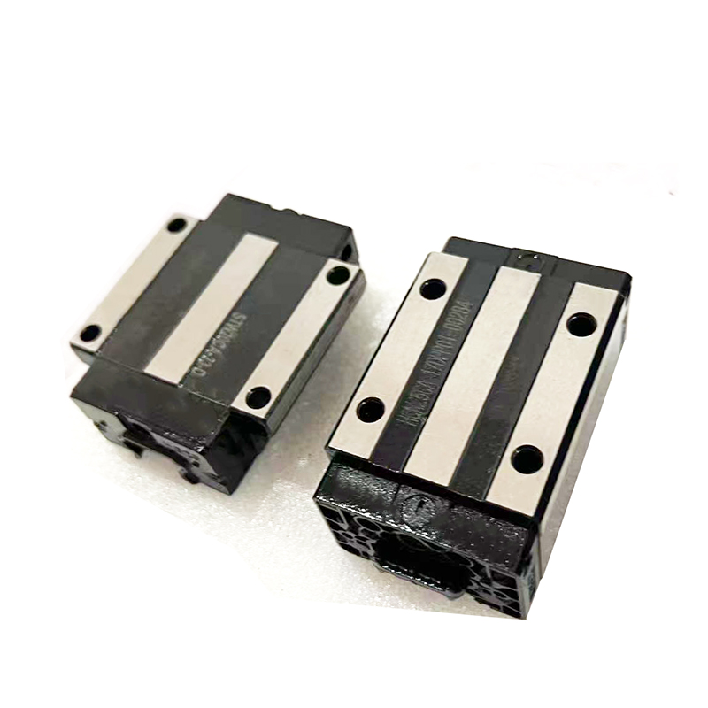
② High Rigidity & Load Resistance
Despite its compact size, the optimized rail and block structure allows the MGN12H to withstand significant axial and radial loads.
It maintains stable motion performance under high-speed movement or sudden load conditions, effectively suppressing vibration and deformation to prevent precision drift.
③ Low Friction & High-Efficiency Motion
Compared with traditional sliding guides, the rolling contact design greatly reduces friction in the MGN12H.
This results in lower driving power consumption and smoother, faster linear motion, making it especially ideal for automated equipment requiring frequent start-stop or high-speed reciprocating movement.
④ Quiet & Stable Operation
Its compact structure and stable ball rolling mechanism produce extremely low noise during operation.
In noise-sensitive applications such as medical devices and laboratory instruments, it provides near-silent linear motion performance.
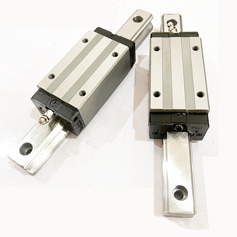
⑤ Flexible Size & Configuration Options
The MGN12H is available in four standard rail lengths: 100mm, 300mm, 500mm, and 1000mm, allowing flexible selection based on equipment stroke requirements.
Shuntai also supports customized configurations according to customer-specific load, speed, and installation space needs, ensuring optimal adaptation to diverse applications.
3. Typical Applications of MGN12H
With its compact size and high precision, the MGN12H has become the preferred linear transmission component in many high-end industries:
Automation Equipment: Positioning axes for small handling robots, precision dispensers, and chip mounters
Semiconductor Equipment: Micro-displacement control for wafer inspection and chip packaging
Medical Devices: Smooth feed for minimally invasive surgical instruments and diagnostic analyzers
Optical Equipment: Focal plane adjustment for microscopes and laser marking machines
3D Printers: X/Y/Z axis motion for desktop and industrial 3D printers
In these applications, the MGN12H delivers stable high-precision linear motion trajectories, meeting strict industry standards for reliability, repeatability, and service life.
4. Why Choose Shuntai MGN12H?
Industrial-Grade Quality: Long-life design, proven for continuous long-hour operation
Fast Delivery: Standard models ship within 7 days, with efficient global distribution from Shanghai Port
Customization Services: Adjustable rail length, block type, and preload level to meet specific requirements
Technical Support: Professional engineering team provides guidance on selection, installation, and maintenance
Conclusion
When your equipment requires high-precision, high-rigidity, low-friction linear motion within limited space, the MGN12H miniature linear guide is a reliable choice.
With mature manufacturing technology and global delivery capabilities, Shuntai has become a long-term partner for many overseas customers.
Whether you are an equipment manufacturer or system integrator, we can provide tailored MGN12H solutions to help your products become more competitive in the global market.
Next Step
Contact our sales team today to obtain the detailed datasheet, quotation, and sample testing plan for the MGN12H.
Let Shuntai miniature linear guides empower your next precision project.


 دعم الشبكة